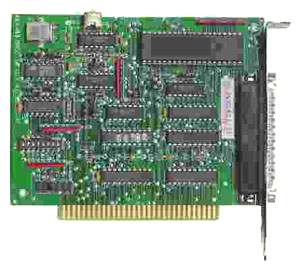
ACCES I/O Products supports critical infrastructure as defined by the US Department of Homeland Security and will be open during normal business hours 6 AM to 6 PM to serve our customers.
We are here to support you.

CTR-05

ISA Bus Counter Timer Card

Features

  • This product has been discontinued. Please contact us for help in finding a suitable replacement.
  • Five independent 16-bit counters
  • Input frequencies up to 7 MHz
  • Up/Down and Binary or BCD modes
  • Internal 1, 2 or 4 MHz counter clock source
  • Programmed frequency output
  • Tapped frequency output
  • Complex duty cycle ouputs
  • Alarm comparators on counters #1 and #2
  • Synchronization of gate and clock inputs to provide improved timing accuracy
  • Software drivers for Quickbasic, C, Pascal, and Windows
  • Designed, made, supported, and manufactured in the USA
The CTR-05 is a low-cost half-size card that contains five general purpose 16-bit counters, a crystal-controlled timebase with dividers, and two 8-bit parallel digital I/O ports. The card plugs into I/O slots in ISA-bus computers. CTR-05 contains the highly flexible type 9513 LSI counter chip, which provides capability for:
  • event count accumulation
  • stopwatch timing
  • frequency-shift keying
  • high-resolution baud rate generation
  • complex pulse generation
  • coincidence alarms
  • time-of-day
  • re-triggerable digital one-shots
  • programmable duty-cycle waveforms
  • programmable frequency synthesis

COUNTERS

The 9513 LSI chip provides a selection of various internal frequency sources Source outputs may be chosen as inputs for individual counters and active-high or active-low polarities are software selectable Each counter may be gated in hardware or by software. Further, the counters can be programmed to count up or count down in either binary or BCD. A LOAD register and a HOLD register is associated with each counter. The LOAD register automatically reloads predefined values into the counter and, thus, controls the effective count period The HOLD register saves count value s without disturbing the counting process, Thus, the host computer can read intermediate values without interfering with the counter. The HOLD register can also be used as a second LOAD register when complex output waveforms are to be generated.

Counters 1 and 2 have additional "alarm" registers and comparators associated with them plus logic for operating in a 24-hour time-of-day mode. For real-time applications, the time-of-day logic will accept 50 Hz, 60 Hz, or 100 Hz input frequencies. Each counter has a dedicated output pin. That output may be turned off when the output is not of interest. The 9513 chip provides considerable versatility for configuring inputs as well as gating of individual counters. This permits dynamic reassignment of inputs under softwar e control and also allows multiple counters to use a single input and allows a single gate input to control more than one counter.

The CTR-05 card includes flip-flops to synchronize gate and clock inputs and improve timing and counting accuracy. You can place jumpers to select either the synchronized or the non-synchronized mode. Further, a second jumper associated with each counter selects either leading edge or falling edge synchronization. Also, CTR-05 contains a means to assure that Read and Write pulses from the computer are at least 400 nS in duration. This feature is activated when a jumper is installed across two programming pins labeled WAIT. While normally not required, this feature is useful for computers with Bus speeds above 6-8 MHz.

CRYSTAL TIMEBASE

An 8 MHz crystal oscillator is provided on the card. Also, a three-stage divider provides means for jumper selection of 4, 2, and 1 MHz clock inputs for the counters.

DIGITAL I/O

The CTR-05 also contains an 8-bit latched parallel digital, TTL input port and an 8-bit latched parallel digital TTL output port. The input port is comprised of transparent D-type latches. When an Enable control signal is high, outputs will follow the inputs; when the Enable signal is low, outputs will be latched at the data levels that were set up. The output port features tri-state outputs designed specifically for driving capacitive or low-impedance loads. Outputs can sink up to 24 mA and can drive 15 standard TTL loads or 60 low-power Schottky TTL loads.

INTERRUPTS

Interrupts from either counter outputs or front external sources are supported. An output from a PAL is connected to any one of interrupt levels IRQ2 through IRQ7 which are user-selected by means of jumpers on the card. An "interrupt enable" signal at the I/O connector enables or disables this Interrupt function. Typically, counter outputs can be jumpered to the Interrupt input at the I/O connector and the Interrupt Enable input can be controlled by one of the digital output bits. This would provide periodic inputs. Alternatively, the Interrupt input can be used for other purposes such as transferring data into or out of the computer, etc.


Available Reference Manuals

Available Software Downloads

Drivers and Downloads

Full list of available Downloads: Software Packages, Drivers, Manuals, and other documents


Custom Software

ACCES also offers Custom Software Services for our products. Our prices are unbelievably low, often as inexpensive as free! If you need something tweaked to support your needs, or an entire enterprise application developed from scratch, it is definitely worth your time to inquire with us, first.

Further information about available ACCES Software:

Redistributing Windows Drivers
A list of ACCES drivers and the files that compose them under different versions of Windows, so you can easily redistribute ACCES cards and drivers.

Specifications


Counter Modes

  • Software-Triggered Strobe w/No Hardware Gating
  • Software-Triggered Strobe w/Level Gating
  • Hardware-Triggered Strobe
  • Rate Generator w/No Hardware Gating
  • Rate Generator w/Level Gating
  • Non-Retriggerable One-Shot
  • Software-Triggered Delayed-Pulse One-Shot
  • Software-Triggered Delayed-Pulse One-Shot w/ Hardware Gating
  • Hardware-Triggered Delayed Pulse Strobe
  • Variable Duty Cycle Rate Generator w/No Hardware Gating
  • Variable Duty Cycle Rate Generator w/Level Gating
  • Hardware-Triggered Delayed-Pulse One-Shot
  • Software-Triggered Strobe w/Level Gating and Hardware Retriggering
  • Software- Triggered Strobe w/Edge gating and Hardware Retriggering
  • Rate Generator w/Synchronization (Event Counter with Auto-Read/Reset)
  • Retriggerable One-Shot
  • Frequency Shift Keying

Inputs

  • Voltage: One LSTTL load
  • Logic High: 2.2 to 5.0 VDC
  • Logic Low: -0.5 to 0.8 VDC
  • Hysteresis (Source & Gate): 0.2V min., 0.3V typical
  • Maximum Input Frequency: 7 MHz

Outputs

  • Counter Outputs: Can sink 3.2 mA and source 200 uA
  • Frequency Out: Can sink 3.2 mA and source 200 uA.
  • Digital Output Port: Can drive up to 15 standar d TTL loads or 60 low-power LSTTL loads.
  • Crystal Stability: ±30 ppm typical (±50 pmm max.) @ 25 °C, ±5 ppm/year

Environmental

  • Operating Temperature: 0 to +50 degree C.
  • Storage Temperature: -25 to +85 degree C.
  • Humidity: 0% to 95% non condensing.
  • Size: 5.0 x 4.25 inches.

Power Requirements

  • +5 VDC at 400 mA typical

Regulatory Compliance

  • This product is in full compliance with CE requirements.


ModelPrice (USD)
CTR-05178.00

Acquisition, Control, Communication: Engineering and Systems