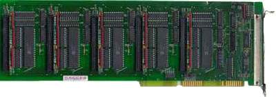
IOD-144
ISA Bus Digital Input/Output Card
Features
- 144 channels of TTL digital I/O lines
- All I/O lines buffered by tristate transceivers. Outputs sink 24mA and source 15mA
- Four- and eight-bit groups independently selectable for I/O
- Pull-up resistors to provide CMOS and contact closure compatibility
- Cable crosstalk suppression by grounds on all even-numbered conductors
- 50-pin connector for compatibility with Western Reserve Controls, Opto-22, Gordos, Potter and Brumfield, etc.
- External interrupts
- Designed, made, supported, and manufactured in the USA

I/O connections are via 50-wire interface cables that extend through rectangular cut-outs in the mounting bracket and plug into headers on the card. Strain relief is provided for these cables. Alternate wires are connected to ground to provide shielding and minimize crosstalk.
The I/O buffers can be enabled/disabled under program control. At each 24-bit port, two of the I/O lines can be used for User Interrupts; one line to enable/disable this function and one for the external interrupt signal. Interrupt levels 2-7, 10-12, 14, and 15 can be jumper selected on the IOD-144.
Card I/O bus address selection is by DIP switches on the cards. The address can be anywhere in I/O space. On power-up or reset, all ports are automatically configured as inputs. This prevents spurious outputs. Before use, of course, the PPI should be software configured by writing to its control register. The table on the previous page defines bit assignments at each PPI.
Downloads
Available Reference Manuals
- View / Download the IOD-144 Manual (.PDF)
- View / Download the Software Reference Manual (.PDF)
Available Software Downloads
Drivers and Downloads
Full list of available Downloads: Software Packages, Drivers, Manuals, and other documents
Custom Software
ACCES also offers Custom Software Services for our products. Our prices are unbelievably low, often as inexpensive as free! If you need something tweaked to support your needs, or an entire enterprise application developed from scratch, it is definitely worth your time to inquire with us, first.
Further information about available ACCES Software:
- Redistributing Windows Drivers
- A list of ACCES drivers and the files that compose them under different versions of Windows, so you can easily redistribute ACCES cards and drivers.
Specifications
Digital Inputs
- Logic High: 2.0 to 5.0 VDC
- Logic Low: -0.5 to 0.8 VDC
- Input Load (Hi): +20 uA
- Input Load (Lo): -200 uA
Digital Outputs
- Logic High: 2.5 VDC min.,source 15 mA
- Logic Low: 0.5 VDC max., sink 24 mA
64 milliamperes optionalPower Output
- +5 VDC from computer bus
Environmental
- Power Required: +5 VDC at 450 mA typical
- Size: 13.1 inches Long
- Operating Temperature Range: 0o to 60 oC
- Storage Temperature Range: -50o to 120 oC
- Humidity: 0 to 90% RH, non-condensing
Regulatory Compliance
- This product is in full compliance with CE requirements.

| Model | Price (USD) |
|---|---|
| IOD-144 | 399.00 |