A1216E
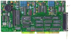
ISA Bus Analog and Digital I/O Card
Features
- Eight differential or 16 single-ended input channels, switch selectable
- Twelve-bit resolution
- 100,000 samples per second
- On-board pacer clock and three 16-bit counter/timers
- Two independent, 12-bit D/A converters
- D/A converter outputs disabled at power-on
- Eight digital I/O lines (4 in, 4 out) accessible at primary I/O connector
- Twenty-four digital I/O lines on an auxiliary connector, configured in two 8-bit ports and two 4-bit ports
- Designed, made, supported, and manufactured in the USA

ANALOG INPUTS
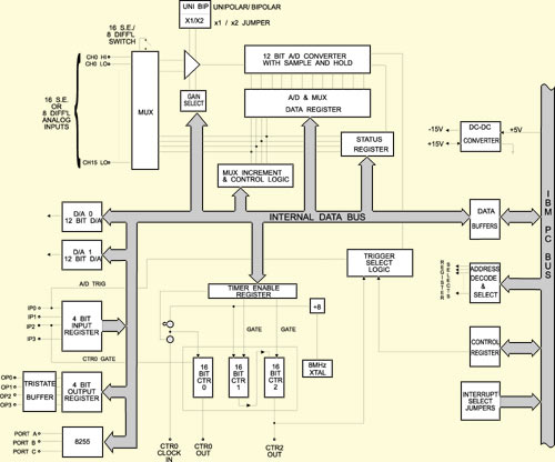
The A1216E card uses a 12-bit successive approximation analog-to-digital converter (A/D) with a sample and hold amplifier input. Under ideal conditions, the A/D can sustain a rate of 100,000 conversions per second. A/D conversions may be initiated in one of three ways:
- by software command,
- by on-board programmable timer, or
- by direct external trigger.
Data may be transferred to the computer by interrupt or program control. Interrupt levels 2-7 as well as 10, 11, 12, 14, and 15 are available by jumper selection.
INPUT SYSTEM EXPANSION
ANALOG OUTPUTS
DIGITAL I/O
Four bits of digital output are available with LSTTL logic levels and 10 LSTTL load drive capability. Discrete outputs OP0 through OP3 provide multiplexer addressing capability for input expansion use, as described previously, or can be used as separate digital outputs. There are twenty-four bits of additional digital I/O available on the auxiliary connector. These bits are arranged in two 8-bit ports and two 4-bit ports. Each port may be independently programmed for input or output.
COUNTER/TIMERS
PIN CONNECTIONS
Downloads
Available Reference Manuals
- View / Download the A1216E Manual (.PDF)
- View / Download the Software Reference Manual (.PDF)
Available Software Downloads
Drivers and Downloads
Full list of available Downloads: Software Packages, Drivers, Manuals, and other documents
Custom Software
ACCES also offers Custom Software Services for our products. Our prices are unbelievably low, often as inexpensive as free! If you need something tweaked to support your needs, or an entire enterprise application developed from scratch, it is definitely worth your time to inquire with us, first.
Further information about available ACCES Software:
- Redistributing Windows Drivers
- A list of ACCES drivers and the files that compose them under different versions of Windows, so you can easily redistribute ACCES cards and drivers.
Specifications

Analog Inputs
- Channels: 16 single-ended or 8 differential, switch selectable.
- Resolution: 12 binary bits.
- Accuracy: 0.1%.
- Input Voltage Modes: ±5V, ±10V, 0-10V
- Input Amplifier Gains: 1, 10, 100, 1000 (Under software control per channel).
- Coding: True binary for unipolar inputs and offset binary for bipolar inputs under jumper control.
- Conversion Time: 8 usec max. (100 KHz throughput)
- A/D Type: Successive Approximation.
- Monotonicity: Guaranteed over operating temperature range.
- Linearity: ±0.9 LSB.
- Zero Drift: ±2 PPM/°C.
- Gain Drift: ±2 PPM/°C.
- Trigger Source: Software Command, On-board Programmable Timer, or External Source.
Analog Outputs
- Channels: Two, independent.
- Type: 12-bit, double-buffered.
- Relative Accuracy: ±1 LSB.
- Output Ranges: 0-2.5V, 0-5V, 0-10V, +2.5V, ±5V, ±10V.
- Settling Time: 15 usec to ± 1 bit.
- Output Drive: 5 mA.
- Output Impedance: 0.5 ohms.
Digital I/0
(8 Bits on Main 37-Pin D Connector)
Inputs:
Outputs:
Digital I/O
(24 Bits on Auxiliary 40-Pin IDC Connector)
Inputs:
Outputs:
Programmable Timer
- Type: 82C54-2 programmable interval timer.
- Counters: Three 16-bit down counters, two concatenated with 1 MHz clock as programmable timer. One counter may be driven by an external input to 10 MHz or driven by internal 1 MHz clock source.
- Output Drive: 2.2 mA at 0.45V (5 LSTTL loads).
- Input Gate: TTL/DTL/CMOS compatible.
- Clock Input Frequency: DC to 10 MHz.
- Active Count Edge: Negative edge.
- Minimum Clock Pulse Width: 30 nS high/50 nS low.
- Timer Range: 2.5 MHz to < 1 pulse per hour.
Environmental
- Operating Temperature Range: 0° to 50°C.
- Storage Temperature Range: -20° to +70°C.
- Humidity: 0 to 90% RH, non-condensing.
- Weight: 10 oz.
- Power Required: +5 VDC, 800 mA.
Size
Regulatory Compliance
- This product is in full compliance with CE requirements.
| Model | Price (USD) |
|---|---|
| A1216E | 529.00 |
| A1216E-S01 | 499.00 |