AD12-8
ISA Bus 12-Bit 8-Input A/D Converter and Counter/Timer Card
Features
- Eight single-ended analog inputs
- 12-bit resolution
- Up to 40,000 conversions/second
- Programmable scan rate
- Can be used with AIM-16 to support up to 128 differential inputs with programmable gains
- On-board counter/timer for event counting, pulse and waveform generation, and frequency measurement.
- Sixteen bits of digital I/O
- Buffered precision reference voltage output
- Designed, made, supported, and manufactured in the USA
Model
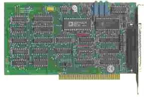
AD12-8 is an 8-channel, 12-bit Analog-to-Digital converter
(A/D) and counter/timer card for ISA-bus computers.
The card is 7.0" long (178mm)and requires a full-size
expansion slot. All connections are made through a
standard 37-pin male connector. Address setup is via
DIP switches on the card.
INPUT SYSTEM EXPANSION
The
AD12-8 contains two control registers for controlling
up to eight 16-input multiplexer expanders model AIM-16.
This provides capability for up to 128 differential
inputs and different gains for each channel
of those multiplexers. Thus, you can mix widely different
full-scale inputs on a channel-by-channel basis.
For for applications where negligible time skew between channel samples is desired, AD12-8 can be used in conjunction with Simultaneous Sample and Hold Card models SSH-xx. Further, if aliasing of the analog input signals is a consideration, then AD12-8-S03 can be used with Anti-Alias Filter Card model AAF-xx.
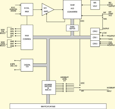
ANALOG INPUTS
Inputs
to the A/D are single-ended with common ground and
can withstand ±30 VDC overload and transients
of several hundred volts. The A/D is a successive-
approximation type converter with solid-state input
analog multiplexer and sample and hold amplifier.
Full scale inputs of ±10 Volts, 0-10 Volts, and
±5 Volts are jumper selectable and provide resolution
of 4.88mV and 2.44mV respectively. A/D conversion
time is typically 25 microseconds.
COUNTER TIMERS
An
8254 counter/timer chip that contains three 16-bit
counters is included. By means of a jumper, you can
set up the card to automatically start upon completion
of a counter cycle. Data from the previous conversion
is stored in dedicated registers to be read by the
computer while the conversion cycle is in progress.
Counters #1 and #2 are concatenated to 32 bits for
this purpose and the clock input is derived from a
1/32 multiple of the computer's 14.31818 MHz color
oscillator. In this way, programs are independent
of the computer's CPU or I/O bus clock frequencies
and programs can be transported to other computers
without possibility of timing problems that could
be caused by those frequencies.
INTERRUPTS
AD12-8
can initiate interrupts at IRQ levels 2 through 7.
These interrupts can be initiated either by the A/D
converter's EOC signal at the end of each conversion
or from an external source via Pin 24 of the I/O connector.
Selection of the interrupt source is by jumper placement
and interrupts are enabled/disabled in software. Interrupt
requests are reset by writing to either of two control
registers or by occurrence of a computer Reset signal.
That latter removes any interrupt request that may
occur at system power up.
DISCRETE DIGITAL I/O
The
AD12-8 also provides sixteen bits of individually
jumper-programmable digital I/O. (Note: If external
AIM-16 expansion multiplexers are to be used with
the AD12-8, seven of these lines are used for channel
selection and gain control. Otherwise, they may be
used as digital outputs.) When set as an output, power
drivers provide 24 mA sink and 2.6 mA source capability.
OUTPUT REFERENCE VOLTAGE
Model
AD12-8 also provides a precision 10 VDC (±0.1
VDC) reference voltage output which is derived from
the A/D converter reference and may be used to provide
sensor excitation when required. This reference voltage
output is buffered and will source up to 220 mA. (Sufficient,
for example, for exciting a number of strain gages.)
Downloads
Available Reference Manuals
- View / Download the AD12-8 Manual (.PDF)
- View / Download the Software Reference Manual (.PDF)
Available Software Downloads
Drivers and Downloads
Full list of available Downloads: Software Packages, Drivers, Manuals, and other documents
Custom Software
ACCES also offers Custom Software Services for our products. Our prices are unbelievably low, often as inexpensive as free! If you need something tweaked to support your needs, or an entire enterprise application developed from scratch, it is definitely worth your time to inquire with us, first.
Further information about available ACCES Software:
- Redistributing Windows Drivers
- A list of ACCES drivers and the files that compose them under different versions of Windows, so you can easily redistribute ACCES cards and drivers.
Specifications
Analog Inputs
- No. of Channels: Eight single-ended inputs w/common ground.
- Voltage Range: Jumper selectable ±10 VDC, ±5 VDC, or 0-10 VDC.
- Overvoltage Protection: ±30 VDC.
- Input Impedance: 10 Megohm or 125 nA at 25°C.
- Accuracy: ±0.02% of reading ±1 LSB.
- Linearity: ±1 LSB.
- Resolution: 12 bit binary.
- Temperature Coefficient: ±10 µV per °C zero stability. ±25 µV per °C gain stability.
- Common Mode Rejection: (When used with AIM-16) 90 db when gain = 1; 125 db when gain = 100
- A/D Trigger Source: Program command, programmable timer, or external trigger.
- Throughput: 40,000 conversions/second max.
Digital Inputs/Outputs
InputsOutputs (DIO 0 thru DIO 7)
- Logic Low: 0 to 0.4V at 8 mA sink.
- Logic High: 2.4 to 5.0V at 0.4 mA source.
Outputs (GN0 thru GN2 and OP0 thru OP4)
- Logic Low: 0 to 0.4V at 24 mA sink.
- Logic High: 2.8 to 5.0V at 2.6 mA source.
- Logic Low: 0 to 0.4V at 8 mA sink.
- Logic High: 2.4 to 5.0V at 0.4 mA source.
Reference Voltage Output
10.0 VDC ±0.10 VDC at up to 220 mA.Counter Timer
- Type: 8254 programmable interval timer, three 16-bit counters.
- Drive Capability: 5 LSTTL loads (2.2 mA at 0.45 VDC).
- Input Load (Gate and Clock): ±10 µA, TTL/CMOS compatible.
- Input Clock Frequency:10 MHz max.
- Active Count Edge:Negative edge.
- Clock Pulse Width: 50 nSec high / 50 nSec low, min.
Interrupts
- Level: Jumper selectable, levels 2-7.
- Enable/Disable: Via software.
- Source: End of conversion or user application.
Environmental
- Operating Temperature Range: 0° to 60°C.
- Storage Temperature Range: _40° to +100°C.
- Humidity: 0 to 90% RH, non-condensing.
Power Required
- +5 VDC at 390 mA.
- +12 VDC at l0 mA.
- -12 VDC at l0 mA.
Size
- 9.0 inches long (178mm)
Regulatory Compliance
- This product is in full compliance with CE requirements.
| Model | Price (USD) |
|---|---|
| AD12-8 | 330..00 |
| AD12-8-S03 | 354.00 |